Substructure Waterproofing
Reliable below-ground waterproofing solutions developed for foundations, basements, retaining walls, lift pits and other critical concrete structures.

Built for Long-Term Structural Protection
A complete waterproofing system designed to protect below-ground concrete structures against groundwater, moisture ingress and hydrostatic pressure.
Our team follows approved method statements, manufacturer recommendations and project quality requirements to provide a reliable and durable waterproofing installation.
Select the Right System for the Structure
Each system is selected according to substrate condition, groundwater exposure, structural detailing and approved project requirements.
Complete Substructure Waterproofing Solutions
Substructure waterproofing protects all building components located below or in contact with ground level, including raft foundations, pile caps, basement floors, retaining walls, lift pits, sump pits, footings, underground parking areas and utility structures. Click any system below to view its applications, installation method, advantages and limitations.
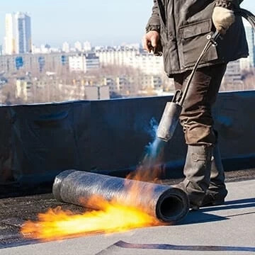
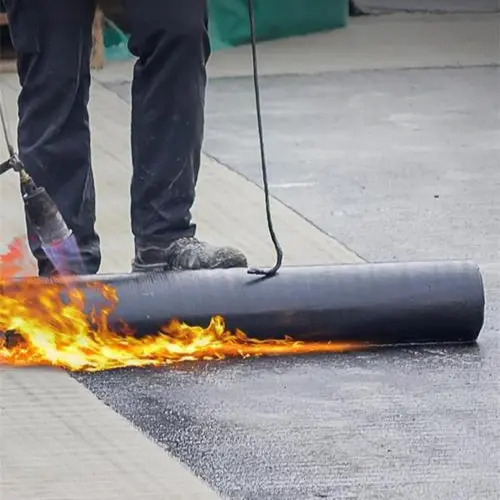
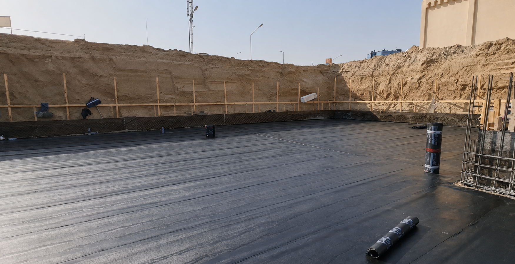
Torch-applied membrane waterproofing is a fully bonded sheet-membrane system commonly used in Dubai for raft foundations, basement walls, retaining walls, pile caps, footings, lift pits, sump pits and other below-ground concrete structures. The membrane normally consists of polyester- or fiberglass-reinforced APP- or SBS-modified bitumen. The approved membrane type, thickness and number of layers shall comply with the project specification and approved manufacturer’s recommendations.
Suitable Applications
- Raft foundations and foundation slabs
- Pile caps, strip foundations and isolated footings
- Basement and retaining walls with external access
- Lift pits and sump pits
- Underground water-containing or concrete structures
- Podium slabs and other below-ground concrete areas
Typical System Build-Up Below Raft Foundation
- Properly compacted formation or approved sub-base
- Plain cement concrete (PCC) or concrete blinding
- Cement-sand levelling and repair mortar where required
- Approved compatible bituminous primer
- Torch-applied bituminous membrane in the specified thickness and number of layers
- Approved protection board, separation layer or cement-sand protection screed
- Reinforced concrete raft foundation
Typical System Build-Up for Basement and Retaining Walls
- Reinforced concrete basement or retaining wall
- Concrete surface repair and corner fillets
- Approved compatible bituminous primer
- Torch-applied bituminous waterproofing membrane
- Approved protection board
- Drainage board or geocomposite drainage layer, where specified
- Selected and approved backfilling material
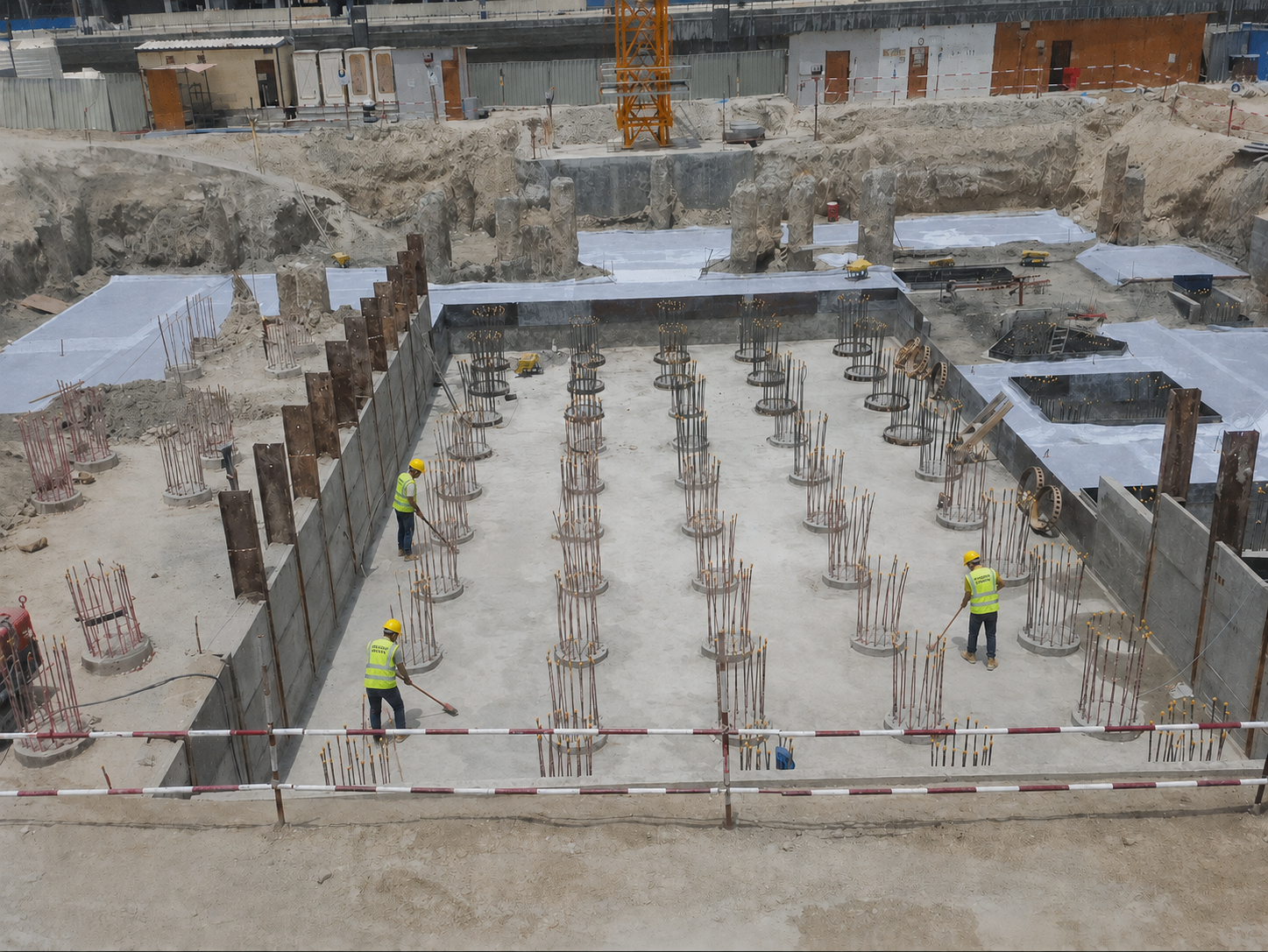
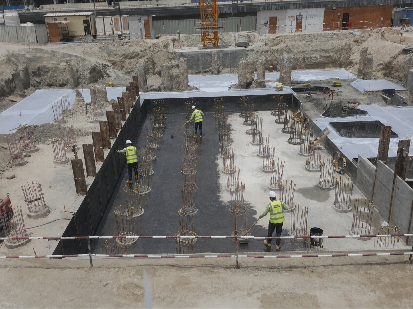
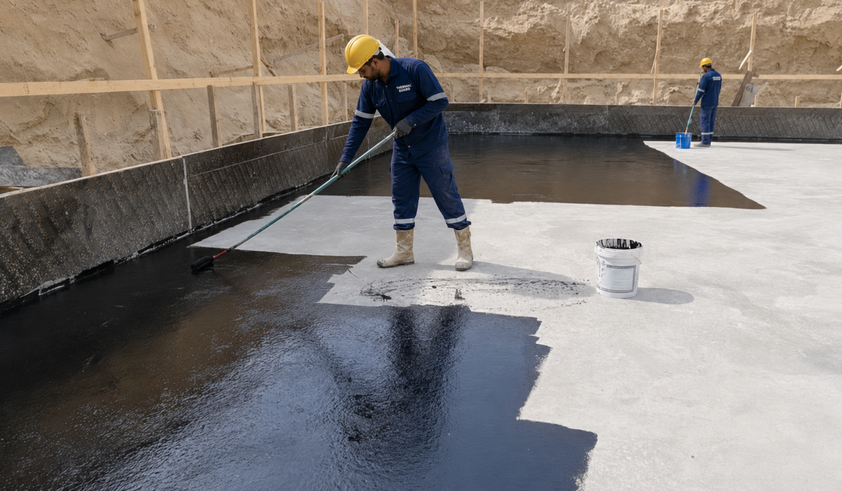
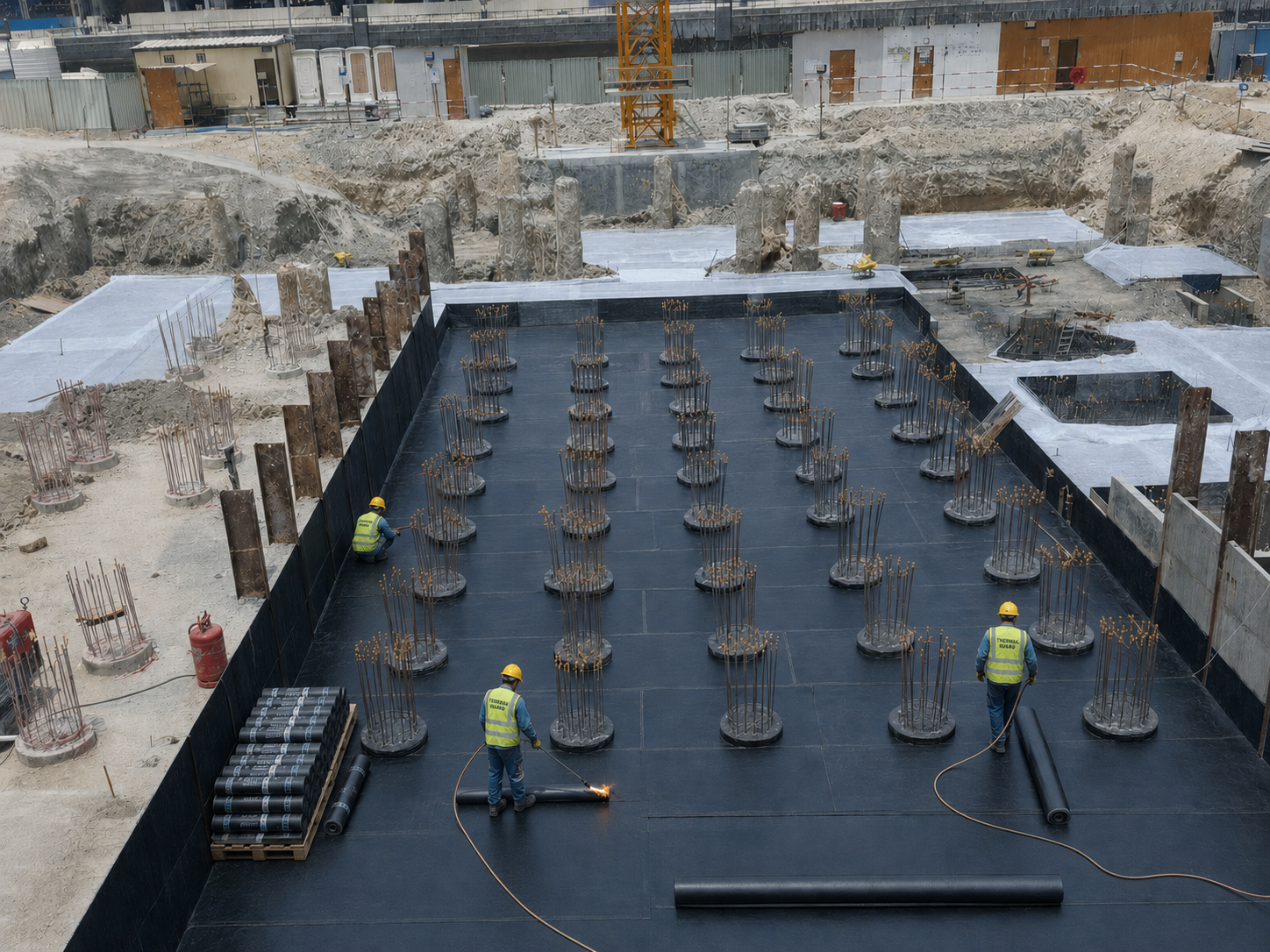
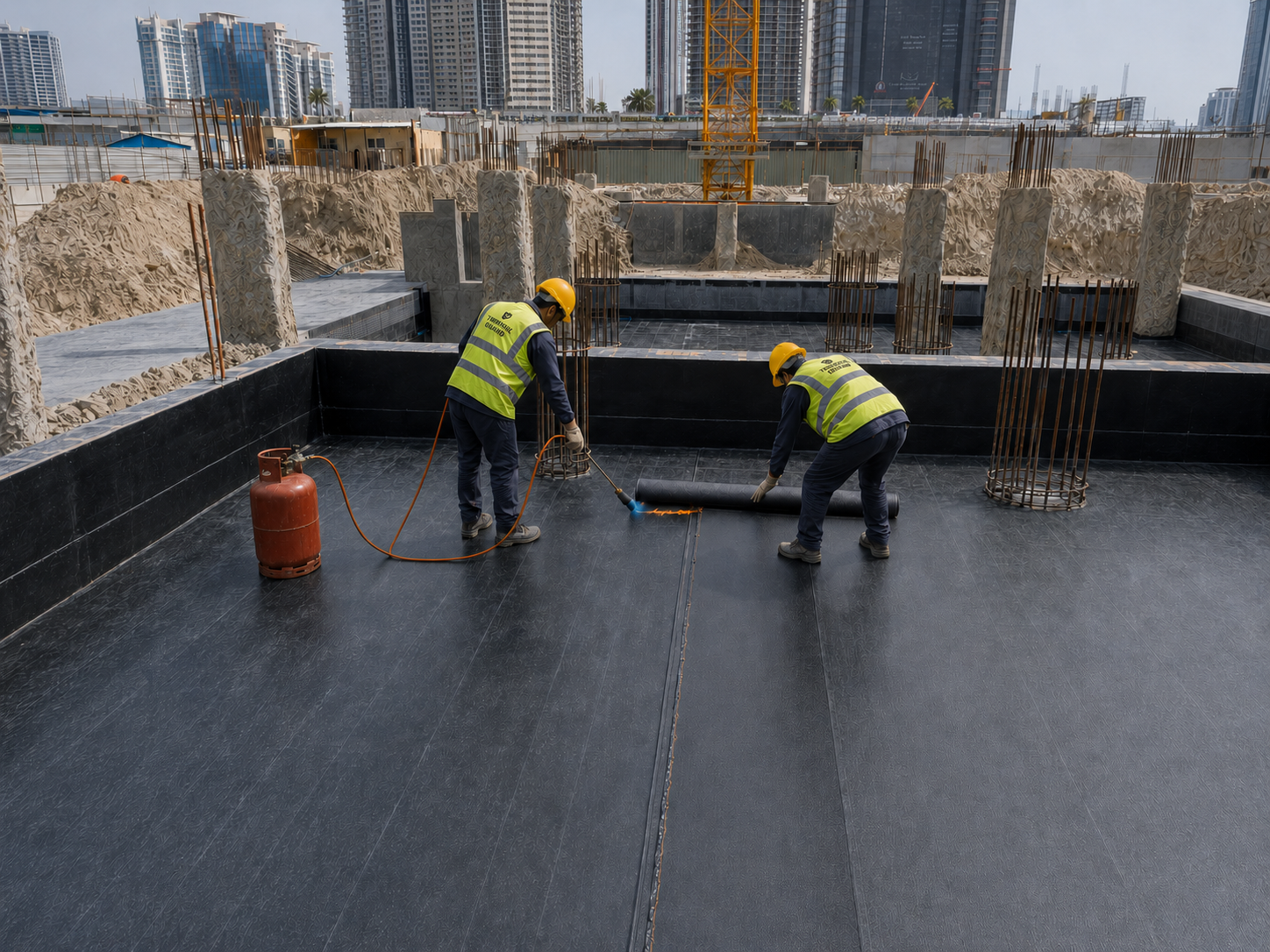
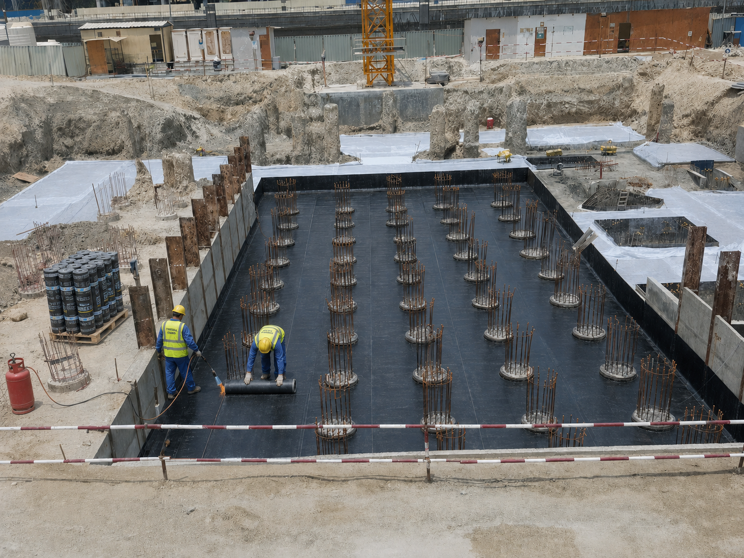
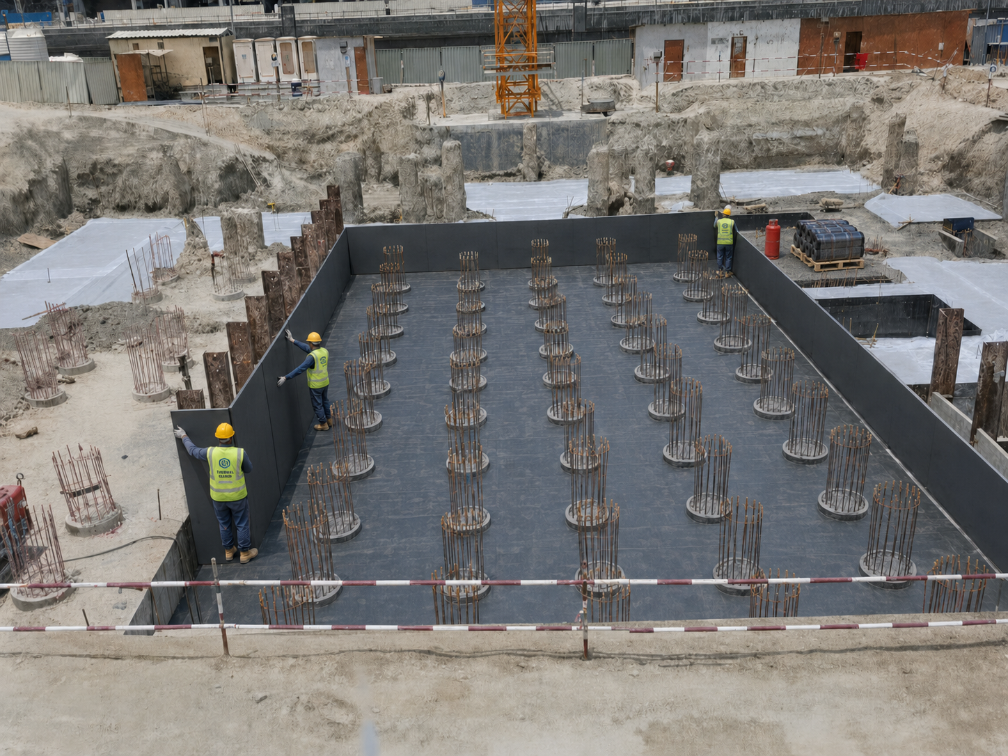
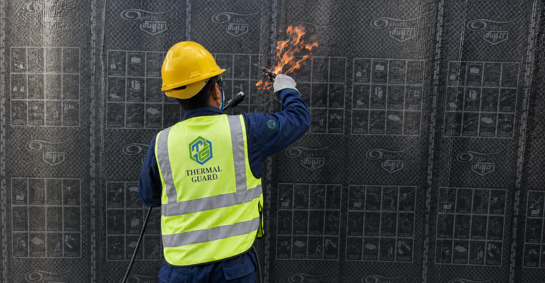
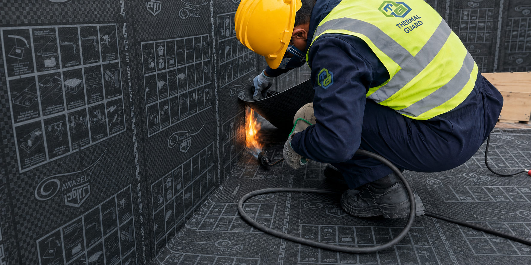
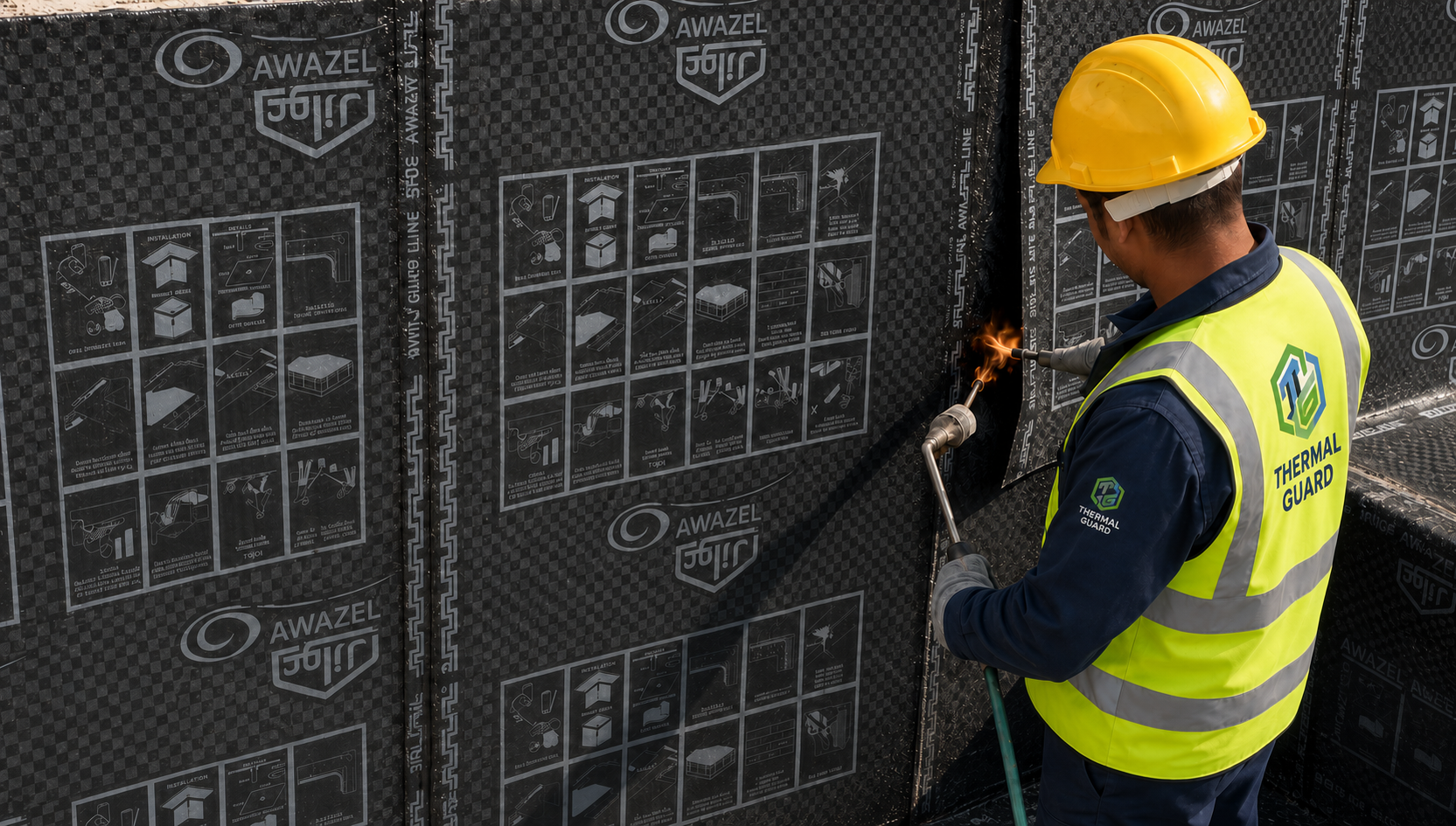
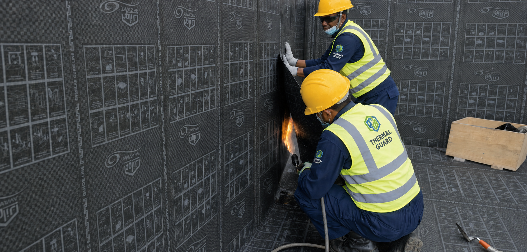
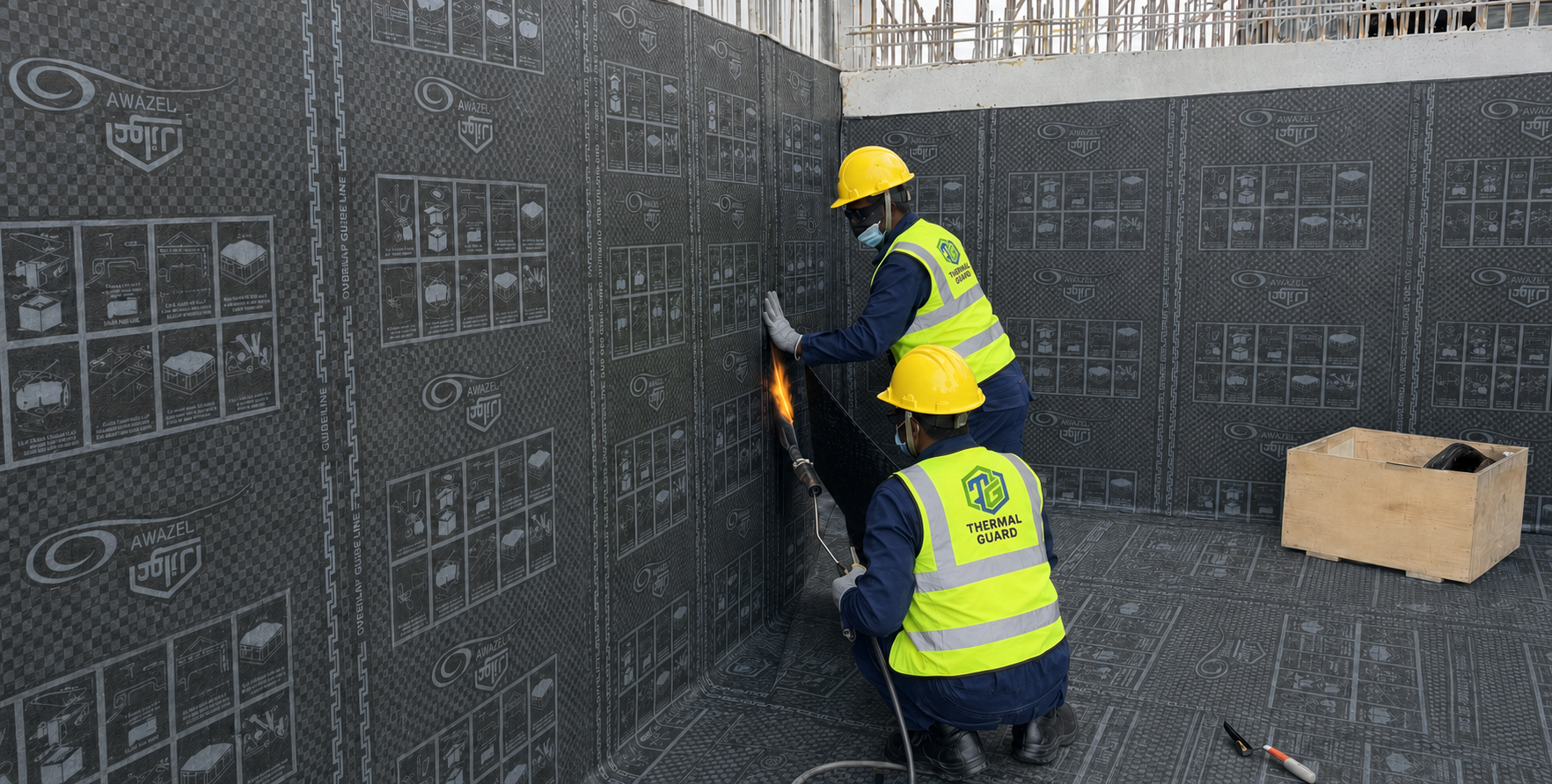
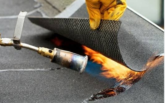
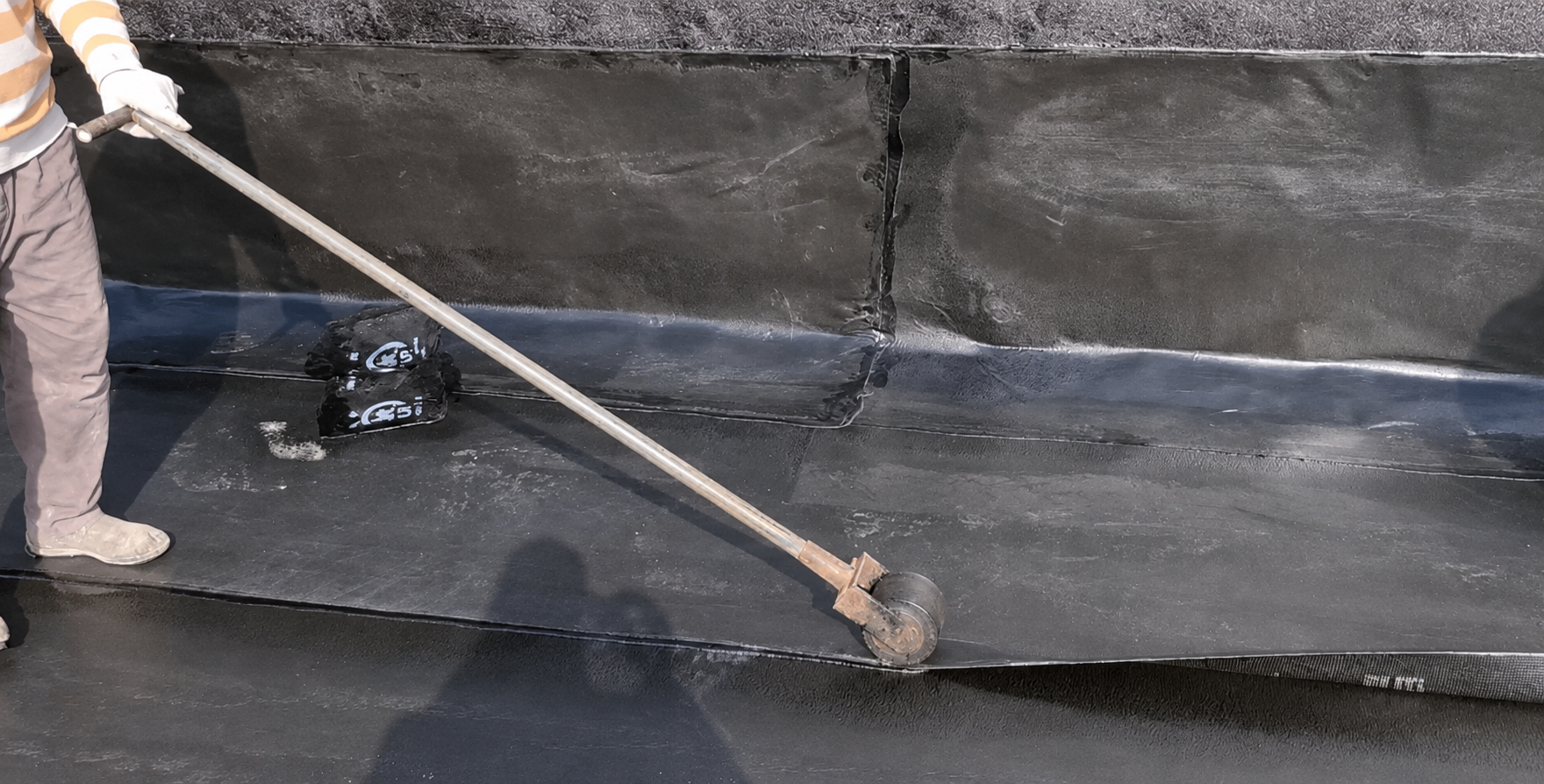
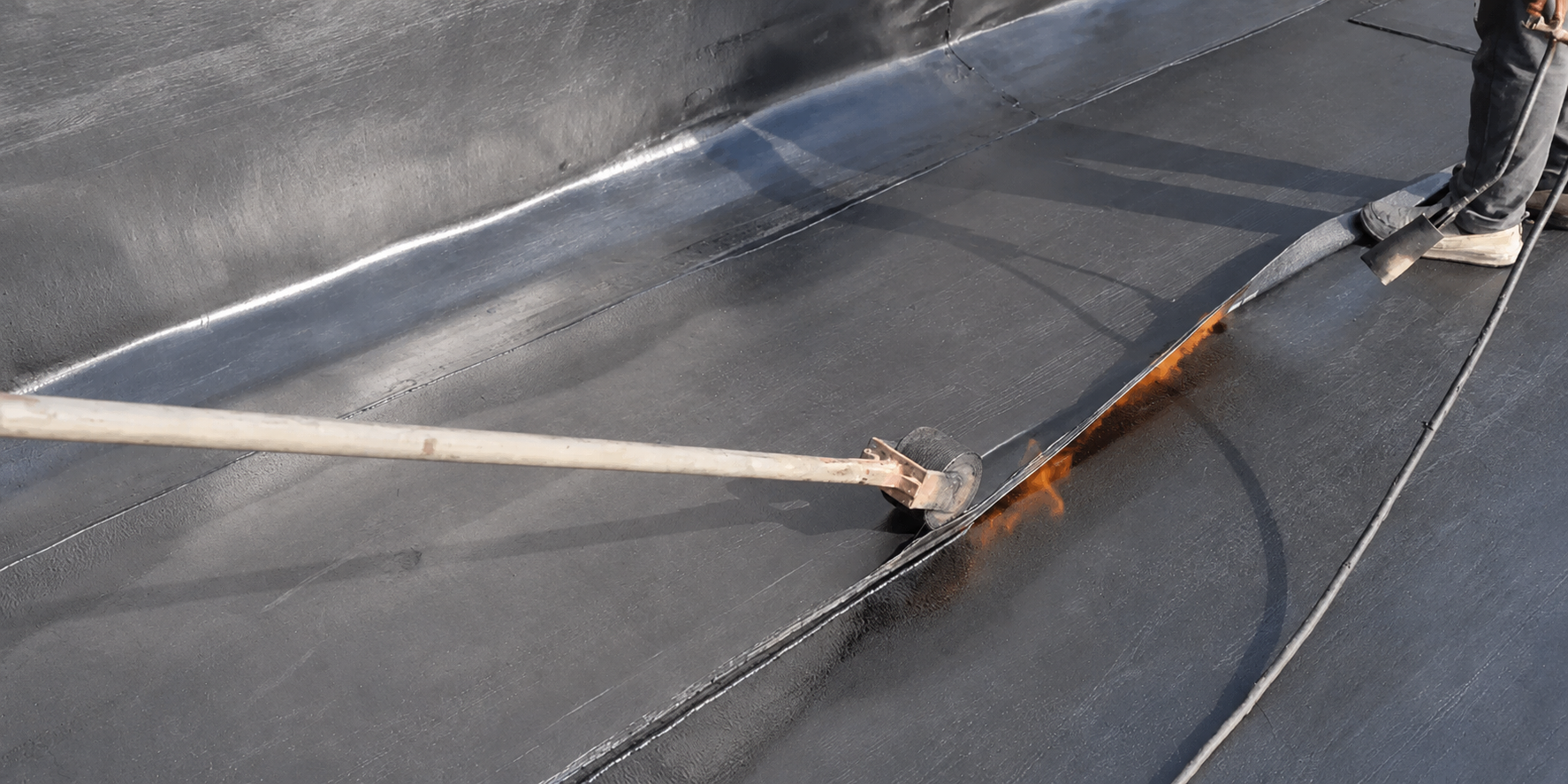
Torch-Applied Membrane Gallery
Click any image to view the full project gallery.

Requirements Before Waterproofing Application
1. Concrete Completion and Approval
- Concrete or blinding must achieve the required curing period and strength.
- The substrate must be inspected and released for waterproofing.
- Honeycombs, cracks, tie-rod holes, blowholes and damaged areas must be repaired.
- Construction joints must be treated according to the approved waterproofing detail.
- Waterstops, hydrophilic strips and injection hoses must be installed where specified.
2. Substrate Condition
The concrete or blinding surface must be:
- Sound, smooth and dimensionally stable
- Clean, dry and free from standing water
- Free from dust, sand, laitance and loose particles
- Free from oil, grease, curing compounds and contaminants
- Free from exposed reinforcement and sharp projections
- Free from excessive depressions or abrupt level differences
3. Surface Repairs
- Remove concrete fins, protrusions and sharp edges by grinding.
- Repair honeycombs and voids using approved repair mortar.
- Fill depressions to prevent membrane bridging and trapped air.
- Seal tie-rod holes using an approved plugging or repair material.
- Stop active water leakage before beginning membrane installation.
- Allow repair materials to cure and dry before applying primer.
4. Corners and Junctions
- Provide approximately 50 × 50 mm cement-sand mortar fillets at internal corners, unless otherwise specified.
- Chamfer sharp external corners.
- Install additional reinforcing membrane strips at corners and changes in direction.
- Do not bend thick bituminous membrane directly over sharp 90-degree corners.
5. Pipes and Service Penetrations
- Install and securely fix pipes, sleeves and puddle flanges before waterproofing.
- Seal gaps around penetrations with approved repair mortar or compatible sealant.
- Provide additional membrane collars around pipes and sleeves.
- Terminate the waterproofing against an approved puddle flange, clamping ring or proprietary detail.
Complete Application and Installation Process
Step 1: Inspection and Setting Out
- Inspect the complete substrate jointly with the contractor or consultant.
- Confirm that civil repairs, corner fillets and penetration works are complete.
- Mark the membrane layout, roll direction, joints, corners and termination points.
- Plan the layout to minimize end joints and prevent four membrane corners from meeting at one point.
- Begin from the lowest level wherever possible and proceed towards higher areas.
Step 2: Surface Cleaning
- Mechanically clean the concrete using a grinder, wire brush, blower or industrial vacuum.
- Remove dust, laitance, loose particles and construction debris completely.
- Confirm that the substrate is smooth, clean and dry before primer application.
Step 3: Bituminous Primer Application
- Apply an approved bituminous primer compatible with the selected membrane.
- Apply the primer uniformly using a brush, roller or approved spraying equipment.
- Avoid excessive primer, ponding and missed areas.
- Properly prime corners, fillets and repaired areas.
- Allow the primer to dry completely and become tack-free before torching.
- Do not apply membrane over wet primer or a damp substrate.
Step 4: Treatment of Critical Details
- Apply additional membrane strips over construction joints where specified.
- Reinforce internal corners, external corners and changes in level.
- Install additional membrane pieces around pile heads, pipes, sleeves and penetrations.
- Treat the raft-to-wall junction according to the approved continuity detail.
- Use a proprietary flexible waterproofing system for movement and expansion joints.
Step 5: Membrane Alignment
- Unroll the membrane over the primed substrate without heating.
- Position and align it according to the approved layout.
- Allow the membrane to relax before installation.
- Re-roll it evenly from one end or from both ends towards the centre.
- Ensure that the torchable polyethylene-film side faces the substrate.
- Stagger the end joints of adjacent membrane rolls.
Step 6: Torch Application
- Heat the membrane underside and primed substrate evenly using an approved LPG torch.
- Move the flame continuously in a controlled sweeping motion.
- Melt the polyethylene film and soften the bituminous compound without burning the reinforcement.
- Slowly unroll the membrane while maintaining uniform heating.
- Press the softened membrane firmly onto the substrate using a roller or suitable tool.
- Ensure complete bonding without wrinkles, blisters or trapped air.
- Maintain a small, continuous bead of molten bitumen at the lap edges.
Step 7: Side and End Overlaps
- Side overlaps: Generally not less than 100 mm
- End overlaps: Generally not less than 150 mm
- The approved product data sheet and project specification shall take precedence.
- Clean and correctly align the overlapping membrane surfaces.
- Heat both membrane faces uniformly.
- Press and finish the joint using a steel roller or rounded trowel.
- Confirm that a continuous bitumen bead appears along the welded seam.
- Immediately reseal any dry, loose or open edge.
Step 8: Second Membrane Layer, Where Specified
- Complete and inspect the first membrane layer.
- Repair blisters, damaged areas and open joints before continuing.
- Offset second-layer joints from the joints of the first layer.
- Do not position the two layers’ side or end joints directly above one another.
- Fully bond the second layer to the first layer unless the approved system states otherwise.
- Avoid overheating or damaging the completed first layer.
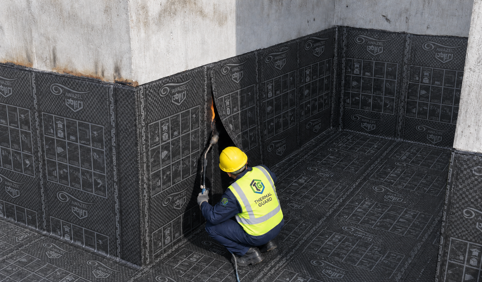
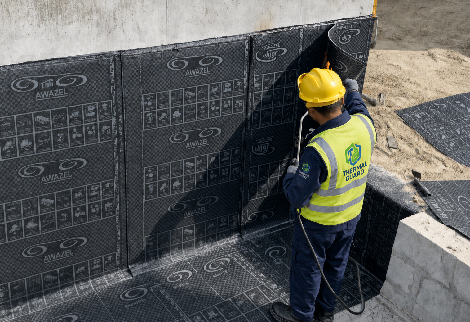
Step 9: Vertical Wall Installation
- Install the membrane from the bottom upward in manageable lengths.
- Fully bond each membrane sheet to prevent slipping and trapped air.
- Connect the vertical wall membrane to the horizontal raft membrane according to the approved detail.
- Maintain the specified side and end overlaps.
- Terminate the membrane inside an approved chase or below a termination bar.
- Mechanically secure the top termination where specified without damaging the main waterproofing area.
- Seal the termination using compatible bituminous mastic or polyurethane sealant.
Step 10: Inspection and Membrane Repairs
Inspect the completed membrane for:
- Open or insufficiently welded overlaps
- Blisters and trapped air
- Wrinkles and fish-mouths
- Burnt or overheated areas
- Punctures, cuts and impact damage
- Unbonded areas
- Incomplete corner and penetration details
Repair localized damage as follows:
- Remove loose or burnt material where necessary.
- Clean and dry the affected area.
- Apply a patch using the same approved membrane.
- Extend the patch at least 150 mm beyond the damaged area on every side, or as specified.
- Torch-weld and seal the complete perimeter of the patch.
- Reinspect the repaired area before installing protection.
Step 11: Watertightness and Integrity Testing
- Conduct flood, ponding or integrity testing where practical and specified.
- Allow the required waiting period before testing.
- Mark and repair any defective or leaking areas.
- Repeat the test after completing repairs.
- Obtain consultant approval before covering the waterproofing.
- Use visual inspection, seam probing or another approved test where flood testing is impractical.
Protection Board Installation
Vertical Basement and Retaining Walls
- Install the approved bituminous, polymeric, HDPE or other compatible protection board.
- Begin from the bottom of the wall and continue upward.
- Place the protection boards closely together without wide gaps.
- Stagger board joints wherever practical.
- Temporarily secure the boards using compatible adhesive, tape or another approved method.
- Do not puncture the membrane using nails, screws or mechanical anchors.
- Cut the boards neatly around pipes and penetrations.
- Install a drainage board over the protection layer where required.
- Ensure that the entire membrane remains protected during backfilling.
Horizontal Raft Areas
Depending on the approved system, protect the membrane using:
- Approved protection board
- Cement-sand protection screed
- Approved separation geotextile
- Another specified protective layer
The horizontal protection layer must withstand reinforcement fixing, worker movement and subsequent construction activities without puncturing or displacing the waterproofing membrane.
Backfilling Requirements
- Obtain consultant approval for the membrane and protection board before backfilling.
- Use selected backfill free from sharp stones, metal, timber and construction waste.
- Do not drop large stones or backfilling material directly against the waterproofed wall.
- Place and compact the backfill in controlled layers.
- Use appropriate light compaction equipment near basement walls.
- Prevent equipment from striking or displacing the protection board.
- Repair visible damage before continuing with backfilling.
Critical Substructure Details
Raft-to-Wall Junction
Extend the horizontal membrane beyond the raft edge to create a sufficiently wide continuity strip. Protect the strip during reinforcement, shuttering and concrete works. Connect it later to the vertical basement-wall membrane according to the approved detail. The continuity strip must not be cut or damaged.
Construction Joints
The membrane system should be supported by approved joint treatment where required, including:
- PVC or rubber waterstop
- Hydrophilic swelling strip
- Injectable hose system
- Additional reinforced membrane strip
Pile Heads
Pile heads require a specially approved waterproofing detail. This may include concrete trimming, polymer-modified repair mortar, crystalline or cementitious waterproofing, hydrophilic strips, compatible liquid-applied waterproofing and membrane termination around the prepared pile head.
Expansion Joints
Expansion joints must be treated using an approved proprietary system capable of accommodating the specified movement. Standard torch-applied membrane must not be used alone to rigidly bridge an active expansion joint.
Quality-Control Checklist
- Approved membrane, primer and accessories are available on site.
- Product batch numbers and shelf life have been checked.
- The substrate has been inspected and approved.
- Surface repairs, fillets and penetration details are complete.
- The primer is uniform, dry and tack-free.
- The correct membrane type, thickness and number of layers are installed.
- Membrane alignment and joint staggering are satisfactory.
- Side and end overlaps comply with the approved requirements.
- All seams are continuously welded and sealed.
- Corners, joints, pile heads and penetrations are properly detailed.
- There are no blisters, wrinkles, burns, punctures or open joints.
- Raft-to-wall membrane continuity is maintained.
- Vertical top termination is properly secured and sealed.
- Required testing and consultant inspection are completed.
- Protection board or protection screed is installed before subsequent work.
Advantages
- Provides a continuous and durable waterproofing barrier.
- Suitable for foundations, basement walls and large below-ground areas.
- Factory-controlled membrane thickness provides consistent coverage.
- Fully bonded application reduces loose areas beneath the membrane.
- Heat-welded overlaps form strong and continuous watertight joints.
- Polyester or fiberglass reinforcement provides tensile strength and dimensional stability.
- Offers good resistance to water penetration and normal construction conditions.
- APP-modified membranes provide good heat resistance for the UAE climate.
- Suitable for single-layer or multi-layer waterproofing systems.
- Allows relatively fast installation over large, open surfaces.
- Localized damage can normally be repaired using compatible membrane patches.
- Widely available and economically suitable for many Dubai construction projects.
Limitations and Important Considerations
- Open-flame installation creates a serious hot-work and fire risk.
- Application must be performed by trained and approved waterproofing applicators.
- It is unsuitable near combustible materials or heat-sensitive services without special precautions.
- The substrate normally needs to be smooth, clean and dry.
- Insufficient heating can cause poor bonding and leaking overlaps.
- Excessive heating can burn the membrane and damage its reinforcement.
- Installation can be difficult in confined, congested or irregular areas.
- The membrane can be punctured during reinforcement, formwork and backfilling works.
- Protection board or protection screed must be installed as soon as possible.
- Damage can be difficult to locate after the membrane has been covered.
- Standard membrane alone cannot accommodate significant structural movement.
- A certified root-resistant system is required for planted or landscaped areas.
- Hydrostatic pressure requires appropriate structural, joint and drainage design.
- Compatibility with sealants, insulation, protection boards and drainage materials must be confirmed.
- The membrane should not remain exposed longer than allowed by the manufacturer.
- Overall performance depends heavily on surface preparation, detailing, seam welding and protection.
Hot-Work Safety Requirements
- Obtain an approved hot-work permit before torch application.
- Keep suitable fire extinguishers immediately available.
- Inspect LPG cylinders, regulators, hoses and torch equipment before use.
- Keep gas cylinders upright and safely away from the flame.
- Remove flammable and combustible materials from the work area.
- Provide adequate ventilation in lift pits, sumps and restricted areas.
- Provide safe access, sufficient lighting and required personal protective equipment.
- Use self-adhesive, cold-applied or other approved detailing near heat-sensitive materials.
- Maintain a fire watch during application and for the period required after hot work finishes.
Recommended Specification
Supply and install an approved APP- or SBS-modified, reinforced torch-applied bituminous waterproofing membrane system to substructure areas. The system shall include preparation of the concrete substrate, compatible bituminous primer, membrane layer or layers of the specified thickness, reinforced treatment to corners, construction joints and penetrations, approved terminations, watertightness inspection and approved protection board or protection screed. All materials and applications shall comply with the approved project specification, manufacturer’s latest instructions and consultant-approved method statement.
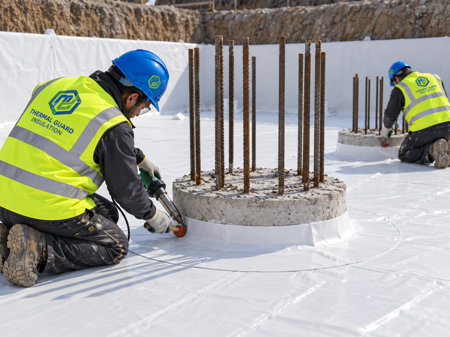
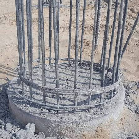
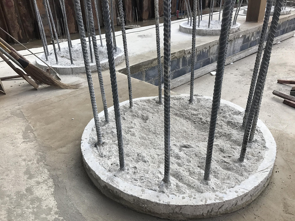
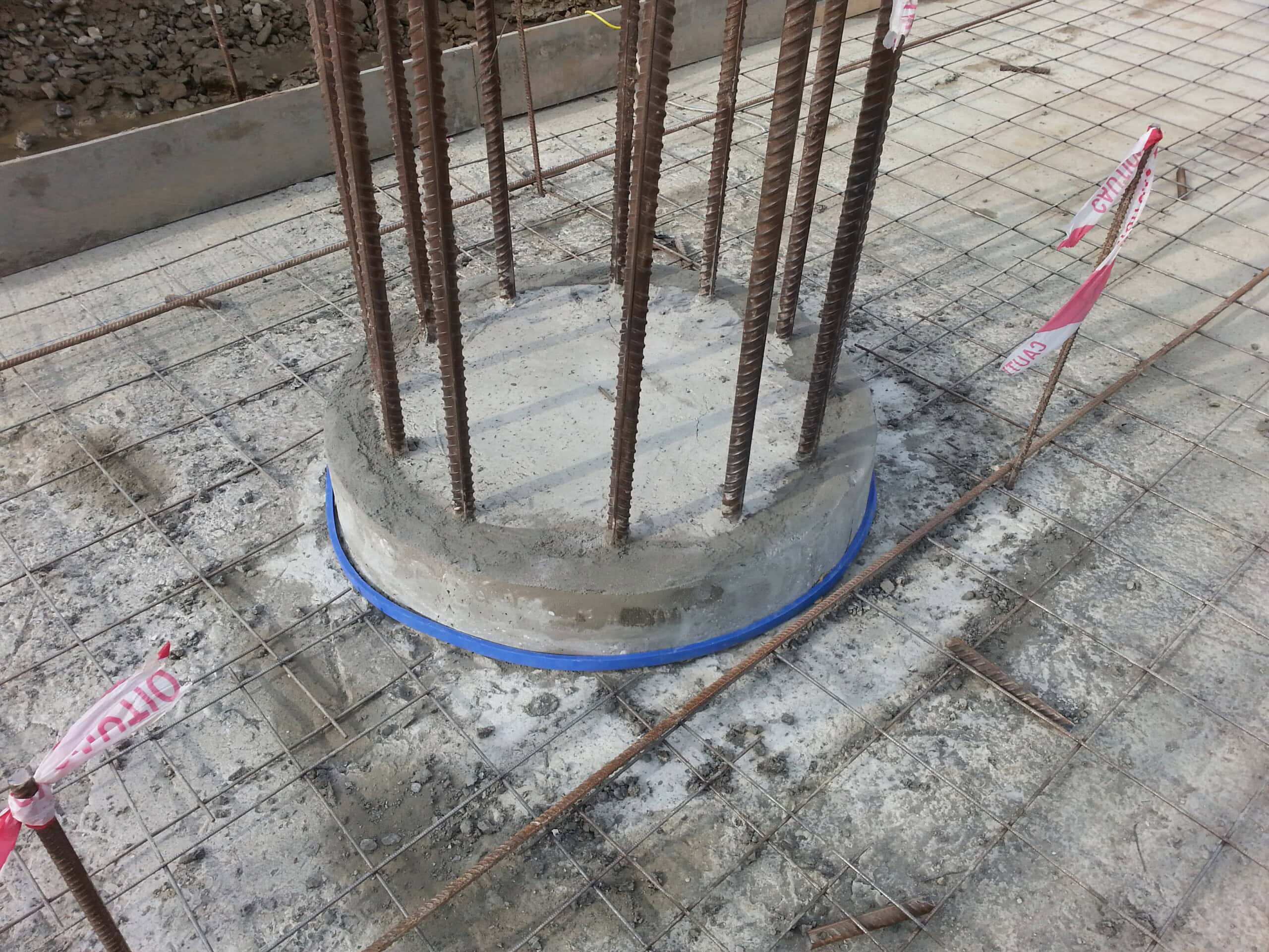
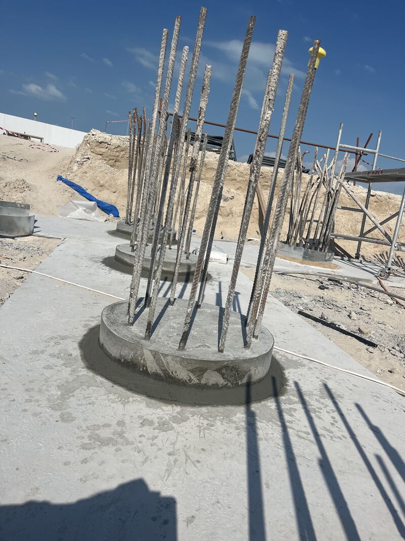
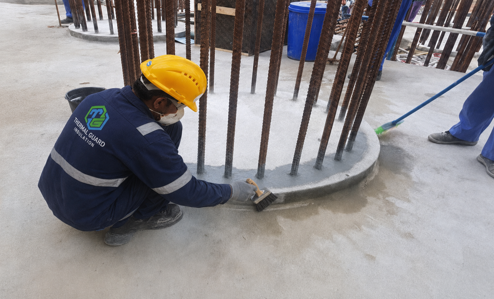
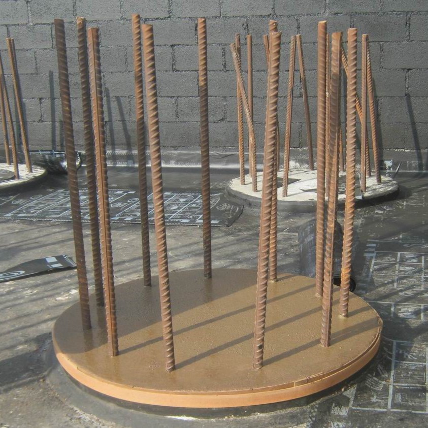
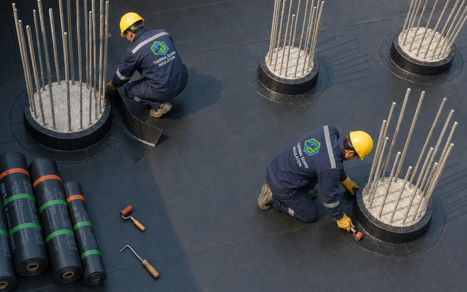
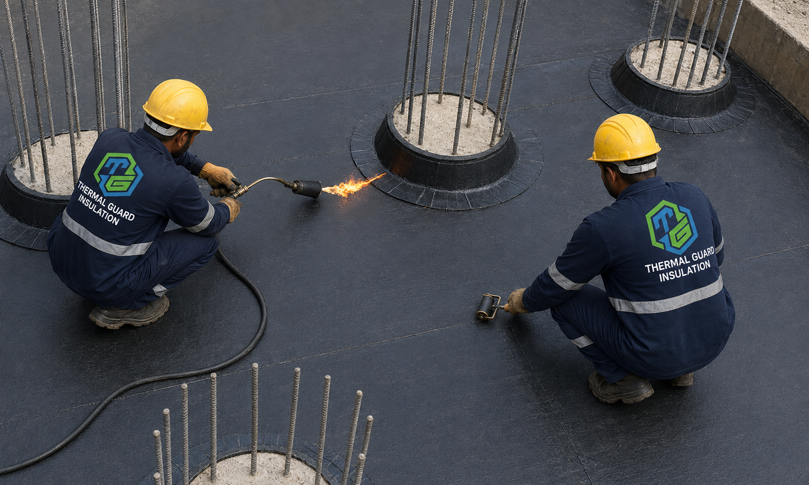
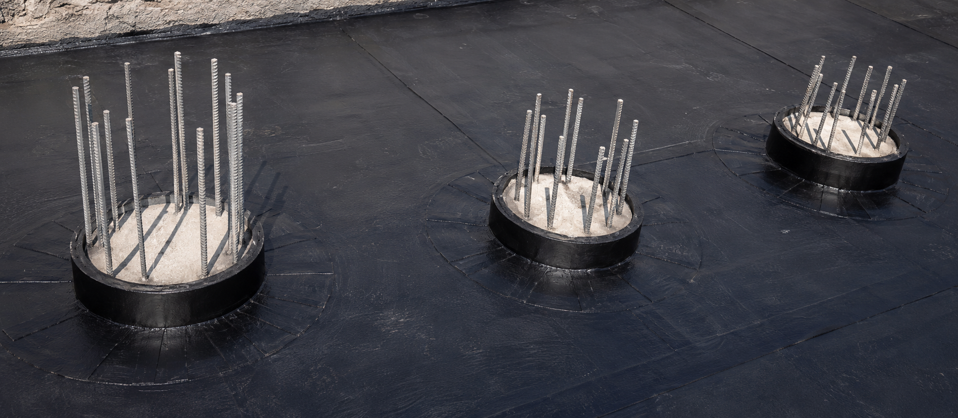
Pile head treatment provides a continuous watertight connection between the pile and the raft waterproofing system. The pile head is carefully trimmed, repaired and cleaned before approved repair mortar, sealing materials and reinforced waterproofing details are applied around the pile perimeter to prevent groundwater ingress.
Typical Application Process
- Trim the pile head to the approved cut-off level and remove weak or loose concrete.
- Clean exposed reinforcement and repair honeycombs, voids and damaged concrete.
- Form a smooth angle fillet around the pile-to-blinding junction.
- Apply the approved primer, crystalline coating or compatible waterproofing treatment.
- Install the specified sealing strip and reinforced membrane detailing around the pile head.
- Seal all edges and inspect the completed treatment before raft reinforcement proceeds.
Pile Head Treatment Gallery
Click any image to view the complete treatment process.
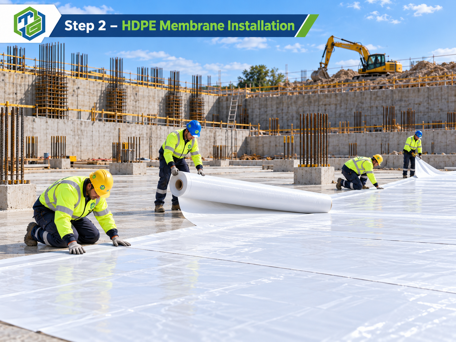
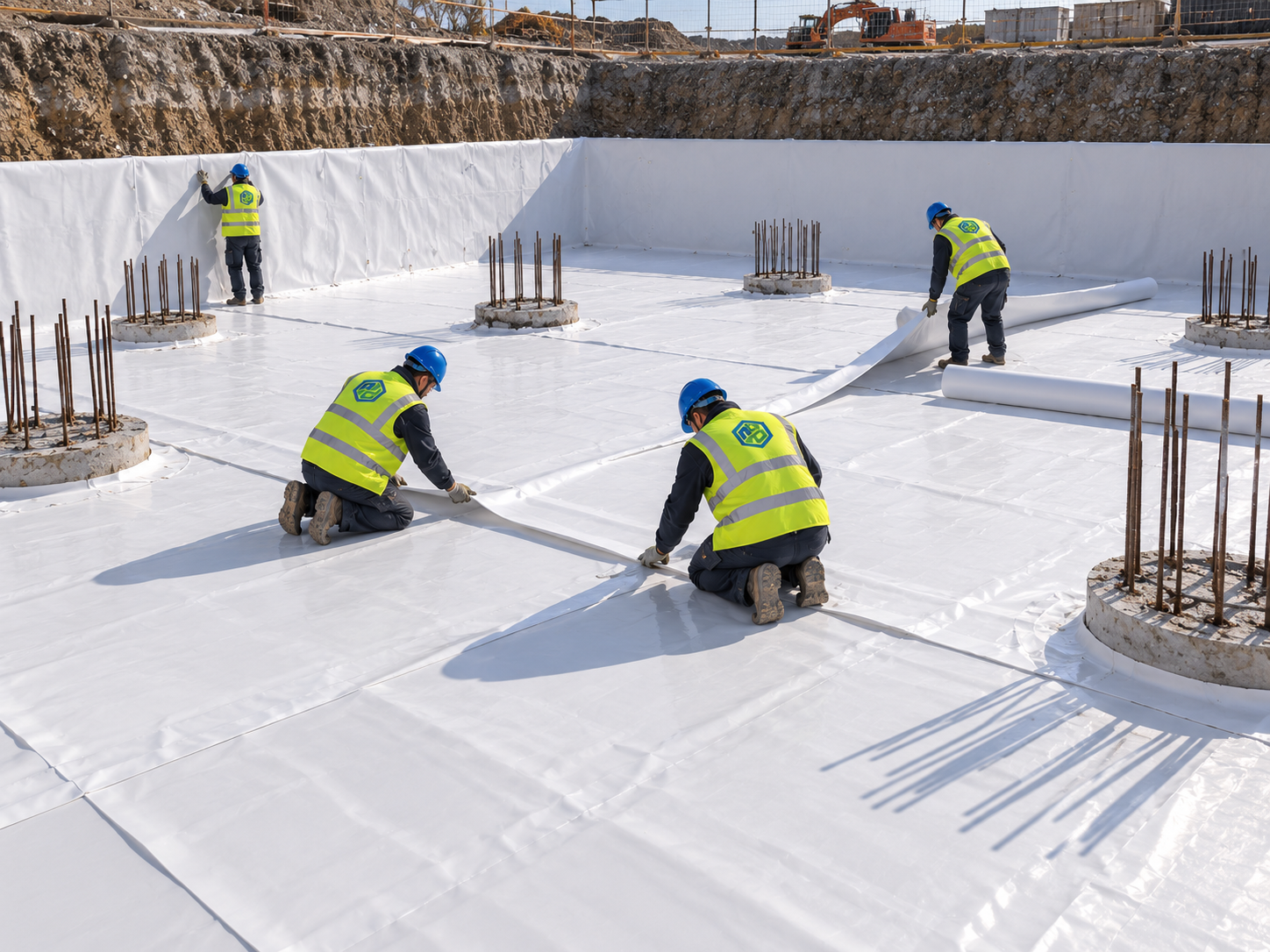
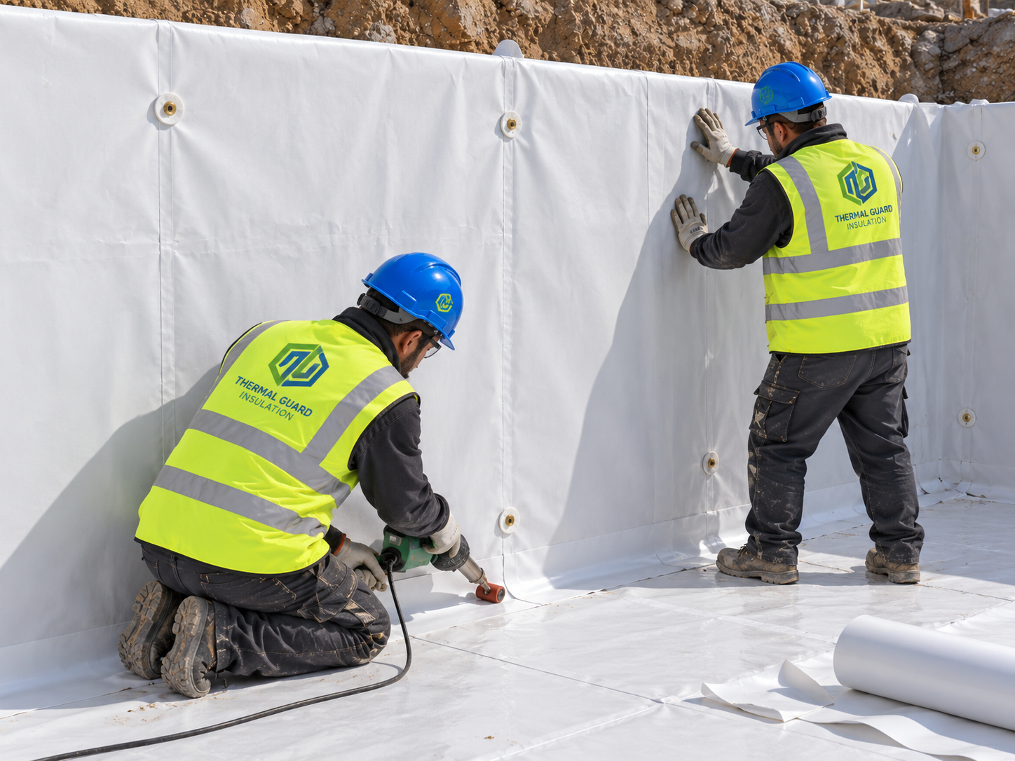
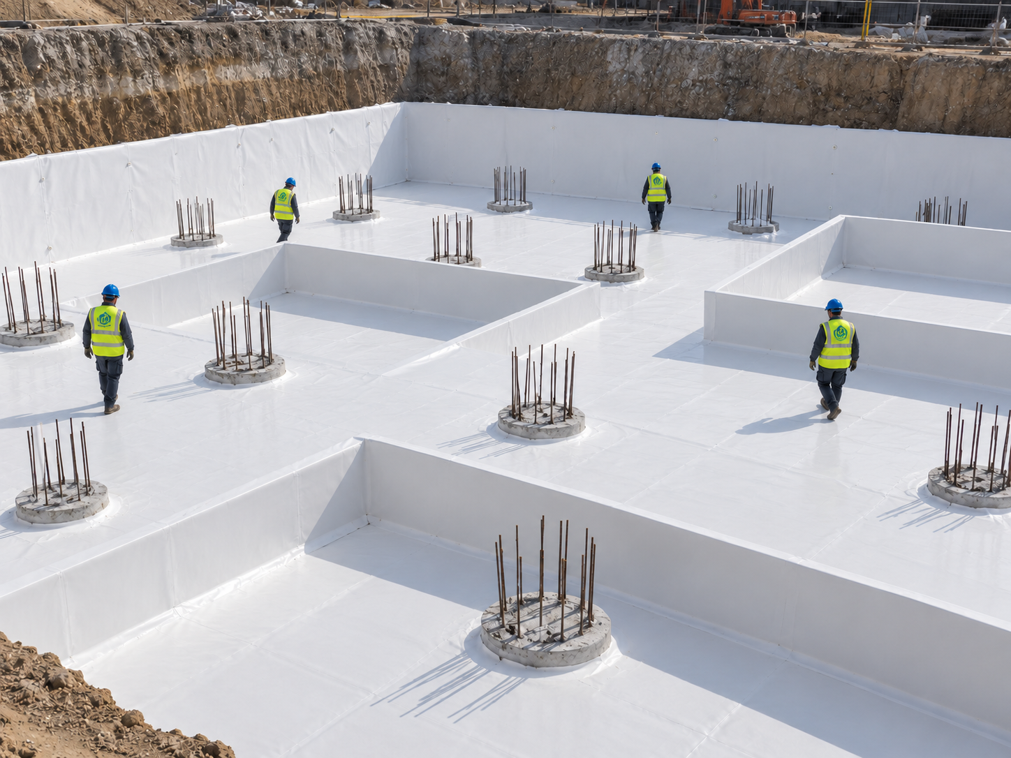
HDPE sheet waterproofing membranes provide a continuous protective barrier for below-ground structures. This installation sequence describes a pre-applied HDPE system, installed over blinding concrete before the reinforced structural raft is cast. The membrane bonding face is oriented towards the subsequent concrete pour.
Complete Application and Installation Process — HDPE Membrane
- Surface Inspection and Preparation: Inspect and clean the PCC/blinding surface. Remove debris, sharp projections and standing water. Ensure a smooth and stable substrate.
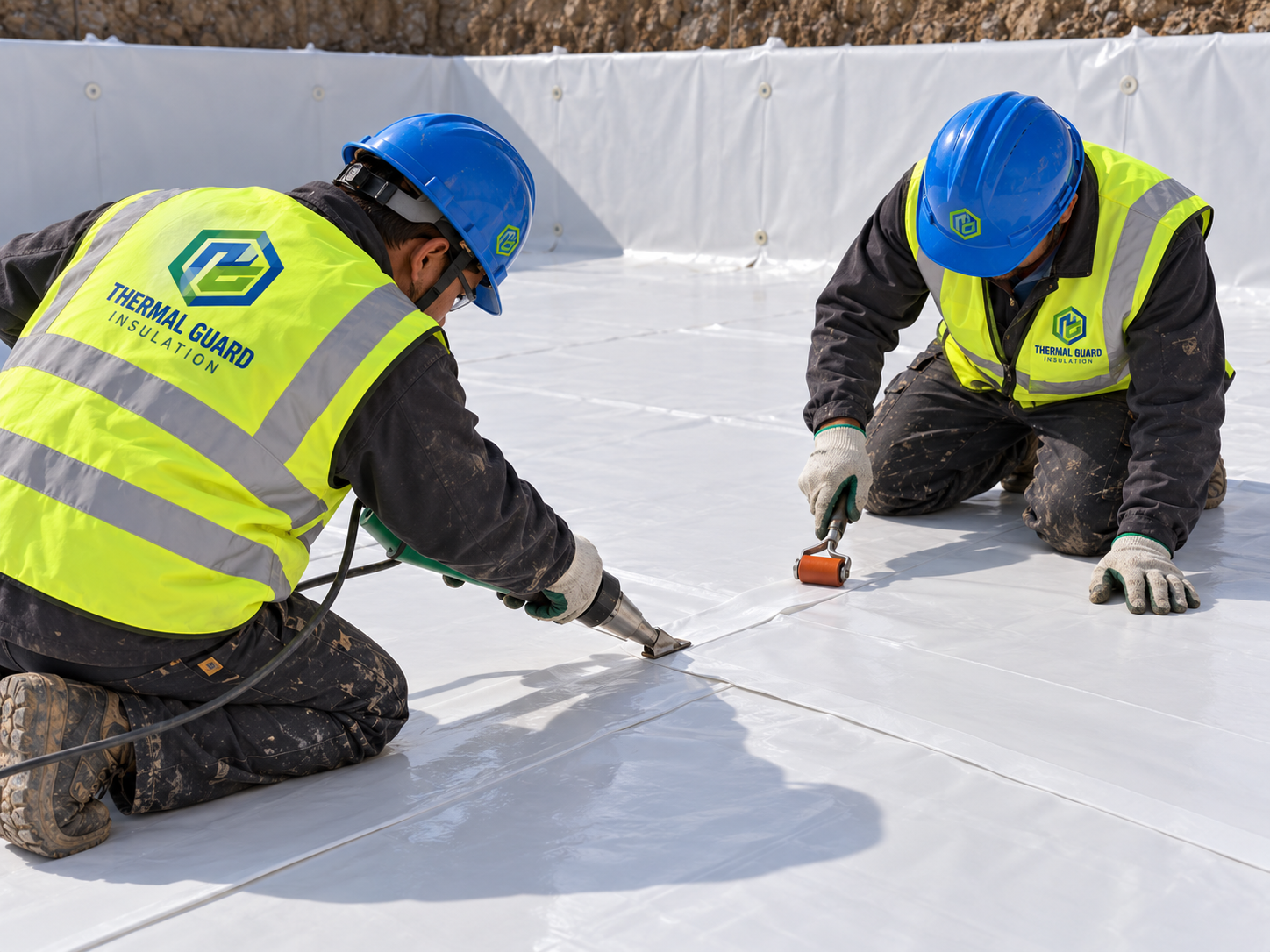
- Installation of HDPE Membrane: Unroll and align the white HDPE membrane over the approved surface, keeping the bonding layer facing the subsequently cast structural concrete.
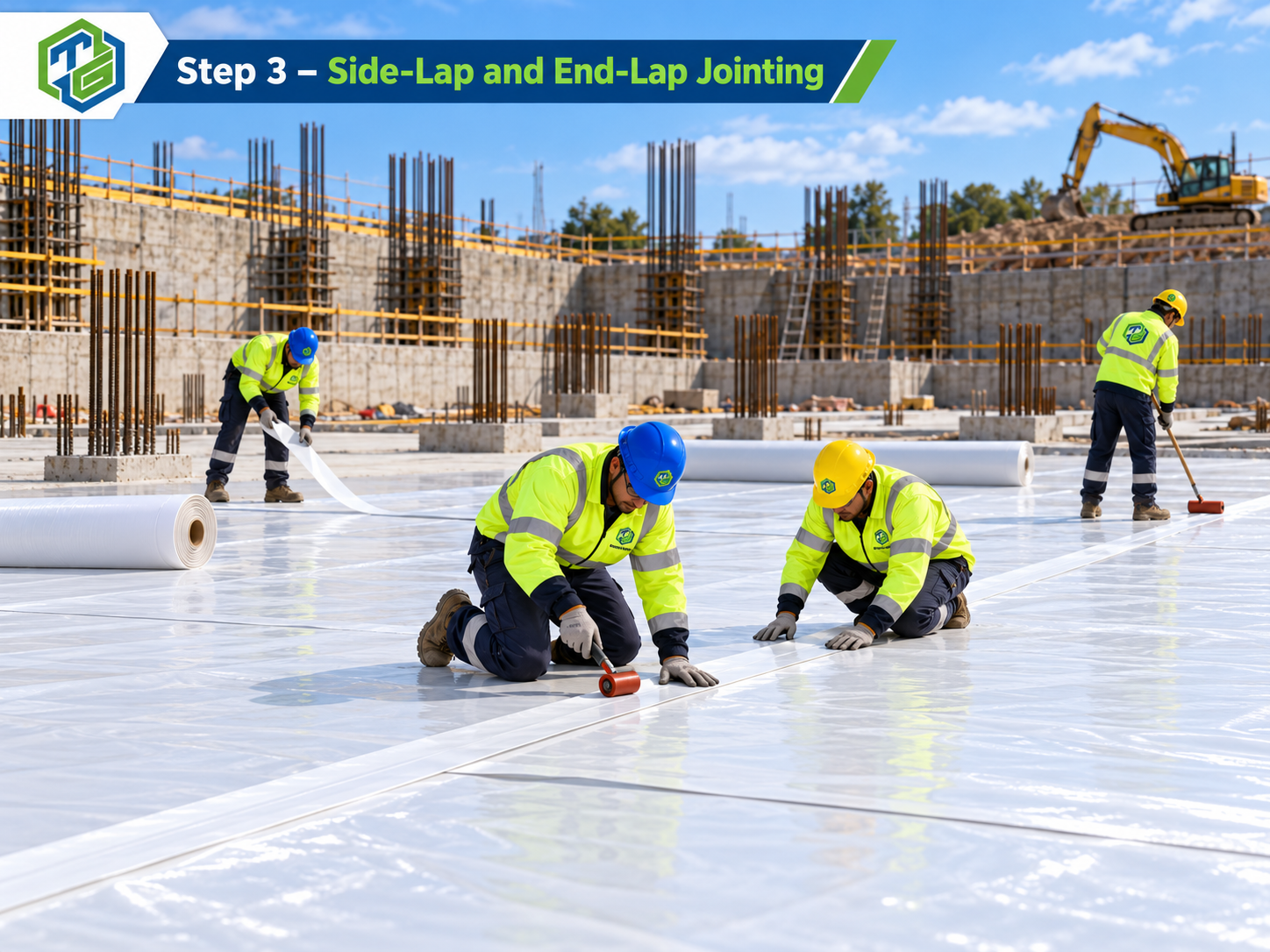
- Side-Lap and End-Lap Jointing: Seal membrane overlaps using manufacturer-approved adhesive tape or welding methods. Press joints firmly to ensure watertight sealing.
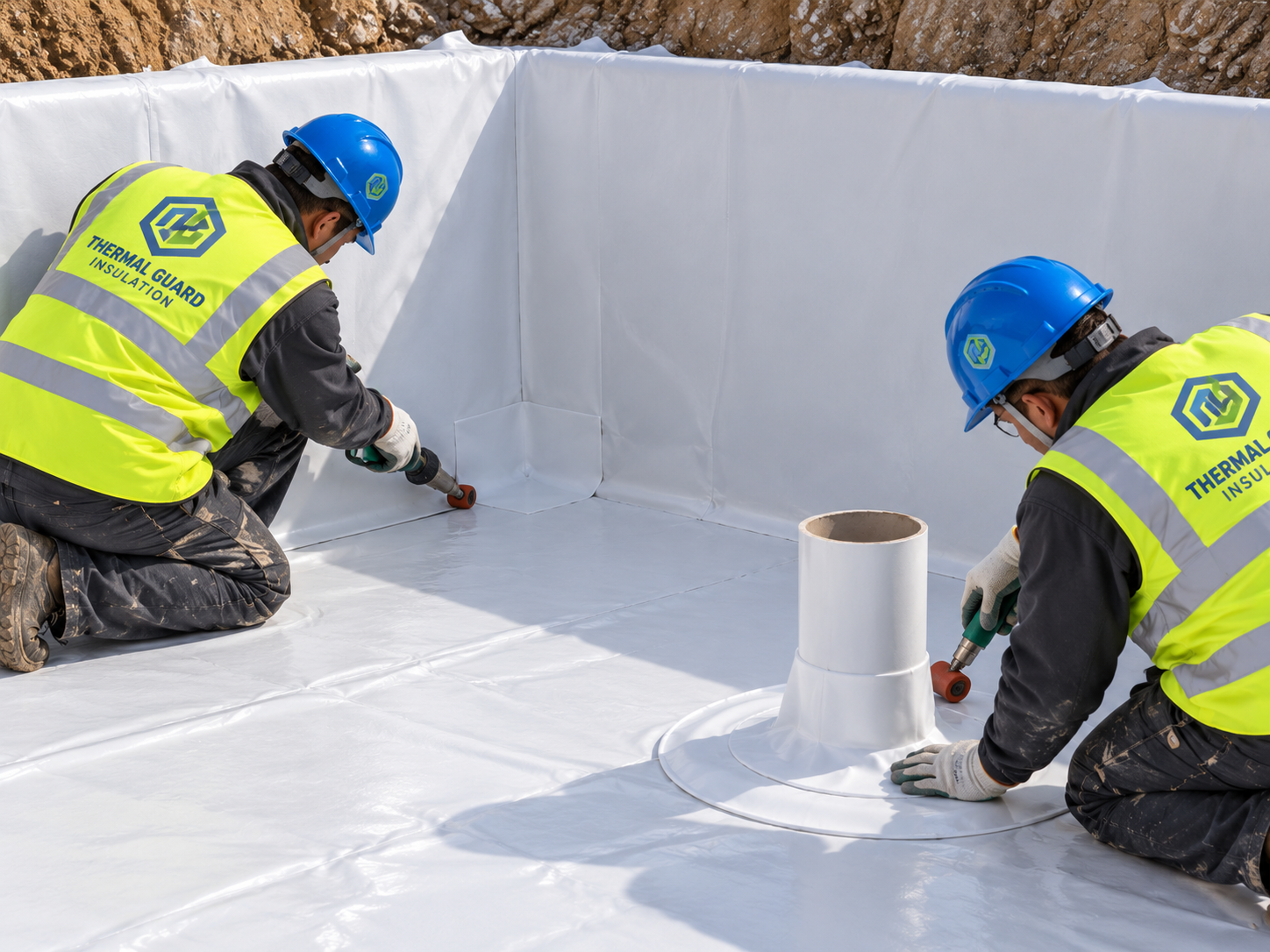
- Corner and Junction Detailing: Provide approved membrane patches at corners, upstands and wall-floor junctions to maintain waterproofing continuity.
- Pile-Head and Penetration Treatment: Waterproof pile heads, pipe penetrations and construction joints using approved sealing materials and reinforced detailing.
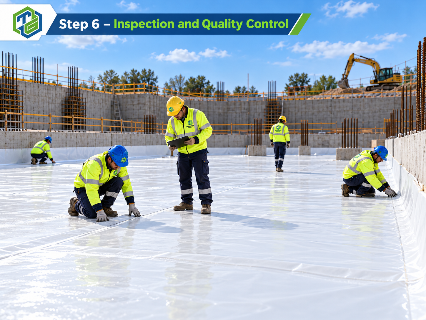
- Inspection and Quality Control: Inspect all overlaps, joints and terminations. Repair any damage and obtain consultant approval before proceeding.
- Reinforcement Installation: The civil contractor installs reinforcement with appropriate supports that do not puncture the membrane. Any damage during reinforcement fixing must be repaired before concrete placement.
- Concrete Casting and Bonding: Fresh structural concrete is placed directly against the exposed bonding surface. Correct concrete placement, consolidation and curing allow the proprietary membrane bonding layer to develop adhesion to the hardened concrete.
HDPE Membrane Installation Gallery
Click any image to view the installation and detailing photographs.